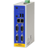
ipRouteDialup
-
Our dial-up adapter ipRouteDialup is an IEC 60870-5-101 based router. ipRouteDialup enables communication via a dial-up connection (PSTN) between a superordinate control station and any device (slave) that does not have its own dial-up functionality.
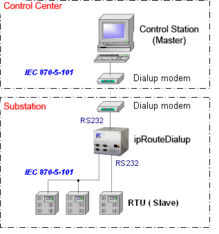
ipRouteDialup supports Hayes compatible analog modems, ISDN and GSM modems. Data transmission is based on the IEC 60870-5-101 protocol, either in balanced or unbalanced mode. The communication mode may be chosen for each direction - uplink and downlink - separately. As one serial interface is reserved for the uplink modem connection, three interfaces are available for connecting substations. These can be operated either in point-to-point or party-line communication (unbalanced).
-
ipRouteDialup supports nearly all the link layer functions defined by
the IEC 60870-5-101 protocol. The various protocols can be combined as
required.
Uplink IEC101DialupSlave
IEC 870-5-101 dialup, slaveFor connecting control stations via a dial-up line. Both, balanced and unbalanced communication is supported. Downlink IEC101Balanced
IEC 870-5-101 balanced, masterFor connecting substations via a conventional serial leased line using balanced mode. IEC101UnbalMaster
IEC 870-5-101 unbalanced, slaveFor connecting substations via a conventional serial leased line using unbalanced mode. The system supports simultaneous connections to several substations.
-
ipRouteDialup offers a full range of functions for communication control, the most important ones are described below.
Connection setup and
teardownipRouteDialup can be called by the control station any time. Once the connection setup is successful, the buffered data is transmitted.
Connection setup can also be initiated by the substation, if the following requirements are met:- The dialup adapter has received an ASDU from the substation - for instance a spontaneous indication - the type of which qualifies for setting up a connection, as defined in the configuration. In addition to the ASDU type, a cause of transmission may be configured, which then initiates the dial-up.
- The telegram buffer (as configured in the size parameter) has been filled to a specified limit.
- In predefined cyclic intervals (configurable).
A configurable character string can be sent to support identification of the substation by the control station.
Connection takedown is initiated if either the maximum idle time (i.e. no ASDUs are sent) or the maximum connection time is exceeded. If the reason for connection setup persists after the disconnection, ipRouteDialup automatically calls again after a configurable timeout.
Intelligent data buffering
flow control
While the uplink connection is down, all ASDUs received by the substations are temporarily buffered. Buffer size is configurable. When a configurable buffer limit is reached, ipRouteDialup sets up a connection to the control station to dispatch the data. When the maximum buffer limit is reached, data transmission is suspended (DFC bit) until the buffer has been emptied to avoid buffer overflow. Special measures are taken to prevent buffer overload by the inflow of measured values. Measured values without a time stamp are entered in a separate impulse buffer where each new value overwrites the older so that only the most recent value for each information object is waiting for transmission. When a measured value with time stamp is received, the relevant entry is deleted from the impulse buffer and the new value is entered directly in the normal buffer. But, if configured, a measured value can still trigger dial-up to the control station.
Accurate monitoring of the ASDUs ensures that a temporary connection break-off or other communication interference does not result in data loss. Unacknowledged ASDUs are repeated after the next connection setup, even if they had been sent before.
Modems ipRouteDialup supports any Hayes compatible modems, analog, ISDN and GSM modems. They can be configured freely via the web interface (for details refer to configuration). ipRouteDialup features automatic modem type detection, so that you may use different vendor modems without having to reconfigure the system.
General poll As the master does not directly register a substation connection failure, ipRouteDialup allows the automatic triggering of a general poll to the substations after the next connection setup. Clock sync ipRouteDialup features clock synchronization for substations. The internal clock can be synchronized via NTP or IEC. Following its own synchronization, any connected substations are synchronized.
-
System configuration is completely executed in a web browser. No other special configuration tools are required, a normal notebook with a network interface card and web browser are all that is needed.
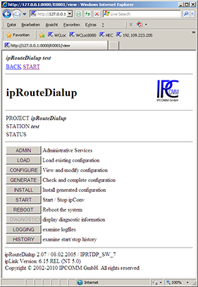
The first page provides access to all relevant functions of ipRouteDialup and shows the general system state at a glance. The following functions are available: - Backup and restore the complete configuration
- Software upgrade
- Edit configuration parameters
- Start up and stop the system
- Access diagnostic data (see also diagnostics)
- Access current log files (see also logging)
System configuration involves only a few parameters. In addition to some general system parameters, such as ASDU address length and information object address length, the link and transport modules need to be configured for each transmission direction. As ipRouteDialup simply passes through ASDUs, information objects need not be configured directly.
ASDU types that initiate dial-up to the control station are configured in a list.
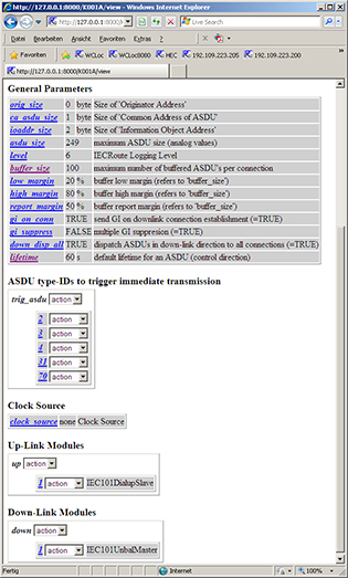
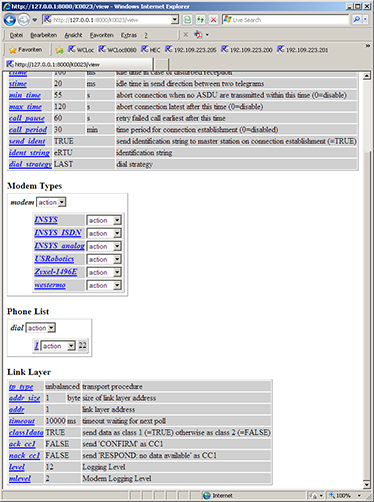
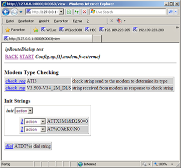
This is the configuration page for the IEC101DialupSlave module which handles communication to the superordinate control station as well as modem control. Eligible modem types can be configured here. All modem types shown in the dropdown list have been tested on the system.
Modem configuration page. Next to the modem detection sequence, the user can enter several character strings that are sent to the modem during initialization. The character string for dial-up to the control station is configured here, too. The dial number is taken from a separate list.
-
The diagnostic display offers a quick and detailed overview of the communication state on all configured connections.
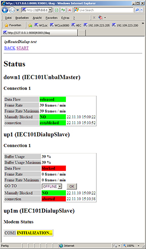
The "Diagnostics" button on the first page provides access to diagnostic information. The most important information is displayed in plain text format with the time in a clear and easy to read way. Colored highlights indicate an ok / not ok status. The relevant information is shown for each connection separately. In addition to information on the communication state of the link and transport layers, statistical data is given. This includes the number of ASDUs transmitted per minute on a specified connection. For uplink connections, the buffer state is displayed to facilitate fast detection of communication bottlenecks.
Connection setup with ipRouteDialup can be initiated from here, or if a connection is up and running, connection takedown which significantly facilitates the commissioning phase.
The current modem state is also displayed.
-
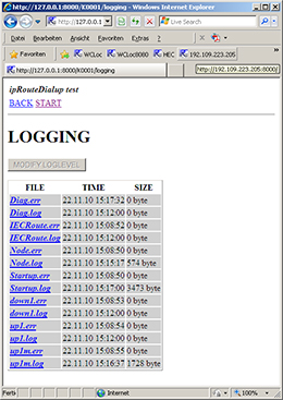
With all communication applications, it is always essential to know which data is transmitted via a protocol and how the data is converted from one protocol to another. And it is even more important when problems occur with transmission. ipRouteDialup features logging and archiving functions for all data traffic.
ipRouteDialup allows you to keep track of the system state and information flow inside the converter by recording and archiving all information passing through a module for a given time period. The following data can be recorded: - All data to/from ipRoute sent and received via the relevant communication module
- System messages, i.e. connection break-off, communication error messages etc.
- Configuration and software error messages
The range of data recorded is defined by the logging level. This can be changed dynamically (at runtime) or statically (in the configuration) for each module.
The logging level defines the representation format for the sent or received information. Data can be represented either in hexadecimal code or in decoded, symbolic form or both. This example shows the content of a logfile generated from the IEC104 server module. Data is stored directly in the easy to read ASCII format. Logfiles can be downloaded via a web interface for offline diagnosis. Or you can keep track of the communication online via the TCP/IP "telnet" service.
All recorded data is archived cyclically, enabling you to keep track of communication over a period of days or even weeks (depending on the data volume).
(2): << [1/1] I-FRAME NS=8377 NR=4 DATA=<01 02 03 00 01 00 0
(2): << [1/1] I-FRAME NS=8378 NR=4 DATA=<01 02 03 00 01 00 0
08.03.05 14:55:11 up1 [1/1] path disconnected !
08.03.05 14:55:11 up1 [1] connection aborted !
08.03.05 14:57:39 up1 [1/1] path connected !
08.03.05 14:57:39 up1 [1/1] connection established with 192.
(2): >> [1/1] LEN=4 STARTDT ACT
(2): >> [1/1] LEN=20 I-FRAME NS=0 NR=0 DATA=<67 01 06 00 FF
(2): >> [1/1] LEN=14 I-FRAME NS=1 NR=0 DATA=<64 01 06 00 FF
(2): << [1/1] STARTDT CON
(2): << [1/1] I-FRAME NS=0 NR=2 DATA=<67 01 07 00 FF FF 00 0
(2): << [1/1] I-FRAME NS=1 NR=2 DATA=<01 02 03 00 01 00 02 0
(2): << [1/1] I-FRAME NS=2 NR=2 DATA=<64 01 07 00 01 00 00 0
(2): << [1/1] I-FRAME NS=3 NR=2 DATA=<01 3B 03 00 01 00 02 0
(2): << [1/1] I-FRAME NS=4 NR=2 DATA=<01 3B 03 00 01 00 01 0
(2): << [1/1] I-FRAME NS=5 NR=2 DATA=<01 3B 03 00 01 00 02 0
(2): << [1/1] I-FRAME NS=6 NR=2 DATA=<01 3B 03 00 01 00 02 0
(2): << [1/1] I-FRAME NS=7 NR=2 DATA=<01 3B 03 00 01 00 01 0
(2): >> [1/1] LEN=4 S-FRAME NR=8
(2): << [1/1] I-FRAME NS=8 NR=2 DATA=<01 01 03 00 01 00 02 0
(2): << [1/1] I-FRAME NS=9 NR=2 DATA=<01 02 03 00 01 00 01 0
-
These requirements ensure successful integration of IEC 870-5-101 systems:
- Common ASDU (CA = Common Address of ASDU) and the information object address (IOA) must be of the same length
- ASDU types used for the control station or substations must be compatible. This can be ensured by matching interoperability lists.
- ASDU addresses must be unambiguous and unique for all connections, multiple assignations are not allowed.
We would be more than pleased to offer our support to assist you in checking these requirements.
-
SEC2
Compact controller mountable on a DIN-rail with a very attractive price
This system is no longer available! -
MEC2
Powerful midrange embedded controller with a GPRS/UMTS cellular modem module (optional)
-
RS-232 Isolator
4 kV isolated RS-232 transceiver for the protection against external influences in compliance with standard IEC 61850-3
Product Wizard 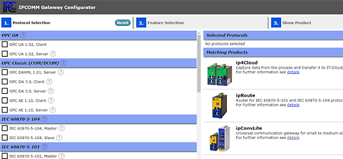
- To the Gateway in a snap
- Get in touch!
- Customer support
+49 911 18 07 91 - 0
support@ipcomm.de
Product consulting
+49 911 18 07 91 - 0
info@ipcomm.de