ipDIO
start price 800,- €

-
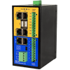
ipDIO is a telecontrol communication device to record digital and analog inputs and to control digital outputs. This high-performance I/O module offers a variety of supported telecontrol protocols. That is why ipDIO can be implemented into each individually designed telecontrol environment.
According to requirements digital or analog information of any device, switch, counter or sensor are recorded or controlled spontaneously or at certain intervals down to millisecond range. ipDIO with its many different interfaces is connected to particular fieldbus systems almost directly or using adapters.
Multiple connections, the combination of different protocols and redundant communication paths are self-evident. The pure value of a data point can be transferred or processed along with the attributes quality and time stamp (protocol dependent).
-
The most important telecontrol protocols are supported to ensure an easy integration into existing telecontrol system. Any combination of the supported protocols enables the realisation of very complex network structures.
Uplink IEC 60870-5-101, Slave - Balanced / unbalanced
- Redundant communication paths
- IEC 101, slave KEMA certified
- Value, time stamp, quality

IEC 60870-5-104, Slave - Multiple parallel connections (control centers) possible
- Redundant communication paths
- IEC 104, slave KEMA certified
- Value, time stamp, quality

IEC 61850, Server - Multiple parallel connections (control centres) possible
- SCL (CID) file export
- Flexible, free configurable data model
- Value, time stamp, quality
Modbus, Slave - Multiple parallel connections over up to four RS-232 or two RS-485 interfaces
Modbus TCP/IP, Slave - Multiple parallel connections (control centres) possible
DNP V3.00, Slave serial/TCP - Multiple parallel connections (control centres) possible
- Redundant communication paths
- Value, time stamp, quality

OPC DAXML 1.01, Server - Direct access from WinCC, InTouch, WEBfactory and others
- Small configuration effort
- WEB based communication
OPC UA 1.02, Server - Direct access from WinCC, InTouch, WEBfactory and others
- Multiple parallel connections possible
- Encrypted communication

As an integral part of the certification procedure OPC UA 1.02, Server was tested in a workshop carried out by the OPC Foundation® with OPC UA clients of many other vendors such as Siemens® - Simatic WinCC V7.4, OPC Labs - QuickOPC 5.36, Unified Automation - ANSI C based OPC UA Client SDK 1.5.1. etc.
Down-Link IEC 60870-5-101, Master
IEC 60870-5-104, Master
Modbus, Master
Modbus TCP/IP, Master
DNP V3.00, Master serial/TCP
-
ipDIO records and reflects switching states, serves as a visualization-, monitoring-, logging- and alarm reporting system and assumes control and regulation tasks.

MirrorDevice
The digital outputs are controlled by the digital inputs of a second ipDIO. In this way, switching signals between two locations are transferred.
PingModul
PING - monitoring of network components to ensure the operational readiness, to log, to visualize and to alert
SNMPClient
SNMP - monitoring of network components with visualization and alerting
Reading of network element variables such as routers, switches, servers, printers, etc.
EventRecorder
All information of interest can be recorded over a period of several weeks, depending on the amount of data.
-
The major communication standards are supported to ensure a simple integration into existing telecontrol engineering. Their configuration is easily carried out via the Ethernet interface using an integrated web server.
A number of templates for protocols as well as functions are available for even easier configuration.
-
The DIAGNOSTICS function shows individual status information of the system during runtime. What information is displayed here depends on the system's configuration, e.g. the configured modules.

-
The SIMULATION function shows all data points in a hierarchical form defined by the configuration. The templates already provide data points to be simulated. The simulation is particularly useful for signal tests during commissioning. This greatly facilitates tracking down of wiring and configuration errors.

-
The function LOGGING provides access to the current and archived log and error files. Log files contain occurred errors, warnings and important status messages. The ipDIO modules (protocols, functions) deliver runtime and status information.

-
The HISTORY function documents the user login and when the software was started or stopped. If the software has stopped because of an error the corresponding entry contains error information like error type or in which module the error occurred.

-
The I/O level is connected via two pluggable screw terminal blocks. LED's at the front of the compact housing indicate the system information (power, CPU). Diagnosis LED's show the signal states of the I/O level (only digital variant).
The SECIO is availabe in two I/O variants:
- only digital (8 digital inputs / 8 digital outputs)
- digital and analog (4 analog inputs / 4 digital outputs / 4 digitale inputs)
- only digital (8 digital inputs / 8 digital outputs)
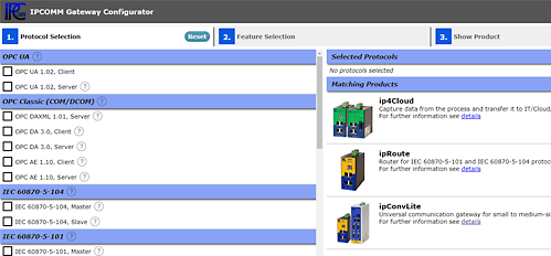
Product Wizard 
- To the Gateway in a snap
- Get in touch!
- Customer support
+49 911 18 07 91 - 0
support@ipcomm.de
Product consulting
+49 911 18 07 91 - 0
info@ipcomm.de
