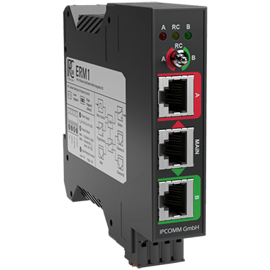
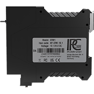
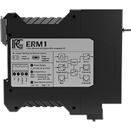
ERM1
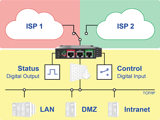
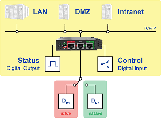
1-Port Ethernet A/B switch with integrated I/O
Power Supply
Voltage: VIN: 24 V DC (VIN: 8 55 V DC, reverse polarity protected)
Current consumption: Max. 150 mA (typ. 3 5 mA)
Ground/protective earth: The ground (GND) is galvanically connected directly to the protective earth (PE)
Line cross-section: 0.129 3.31 mm² (solid or stranded wire)Ethernet relay interfaces
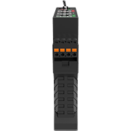
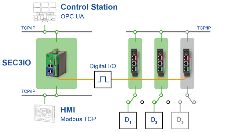
3x RJ45 Ethernet interfaces (A <- MAIN -> B)
(compatible with 10M/100M/1G/10G Ethernet)
At least 100,000 switching operations at a maximum of two switching operations per second.
Power over Ethernet (PoE) pass-through for classes 04 is supported.Function selector switch
(toggle switch)1x 3-way switch to control the ERM1
A: manual MAIN <> Port A
B: manual MAIN <> Port B
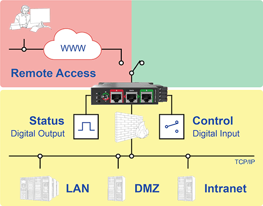
RC: remote control over digital inputDigital input
1x digital control input
Input voltage: 0 24 V DC
(reverse polarity protected VDI_absolute: -60 +60 V DC)
Input level low: ≤ 3.0 V DC ± 10%
Input level high: ≥ 5.0 V DC ± 10%
Input impedance: 1 MΩ ± 5%
Reaction time: ~12 ms
Line cross-section: 0.129 3.31 mm²Digital output
1x digital status output
Output voltage: 0 24 V DC
(VDO_absolute: -55 +55 V DC, Iout: ~0.4 mA)
60 kΩ ± 5% against GND for MAIN <> A
60 kΩ ± 5% against VIN for MAIN <> B
Reaction time: ~7 ms
Line cross-section: 0.129 3.31 mm²Overvoltage protection
The power supply and all interfaces are ESD, surge, and burst protected (see EMC)
Diagnostics (Status LEDs)
A: Switching state MAIN <> Port A
B: Switching state MAIN <> Port B
RC: Remote control via digital inputMaterial
Plastic chassis
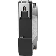
mounting
35 mm DIN-Rail
IP Code
IP30
Rotating parts
None
Dimensions W/H/D
approx. 22.5 mm x 105.5 mm x 123.4 mm
Weight
approx. 0.13 kg
Operating / storage temperature
-40 °C to 85 °C / -40 °C to 85 °C
Rel. humidity
5 % to 90 % not condensing
Approval
CE (Industrial)
Standards
EN IEC 61000-6-2:2019
EN 61000-6-2:2005 +AC:2005
EN IEC 61000-6-4:2019
EN 61000-6-4:2007 +A1:2011
EN 61000-6-5:2015
EN 61850-3:2014
FCC Part 15 Subpart B
ICES-003 (Issue 7)Conformity
RoHS, REACH, WEEE, CE (EMC), UKCA, FCC, ICES